
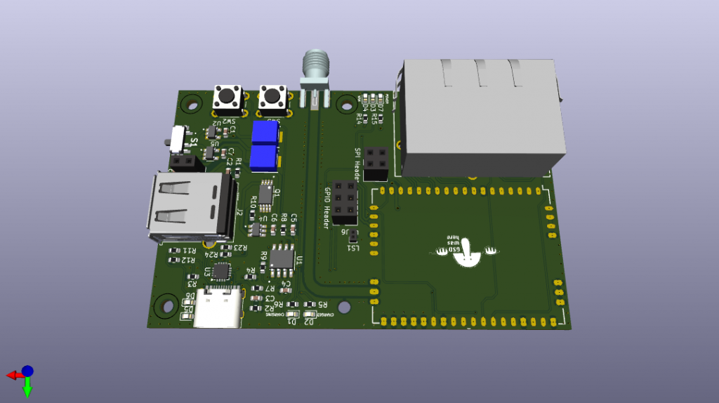
The Micro Router router project was started as part of the Micro Server project. It acts as a mesh network extending the range of the server, or it can be used as a portable range extender for hot-spots or Star-link. It is possible to buy commercial products that act in a similar way but I wanted a system that had a battery for ease of temporary setup, even if the battery does not last too long. I started by sourcing a low power SOM that could run OpenWRT. 8devices seemed to have the only solution, with Carambola 2 SOM meeting all the requirements: low wattage and all the I/O needed. (I will not go into the technical details here since they are listed on the Github page. What is written here is more of a workflow and build log.) It took around a month to draw up the schematic and do the board layout in KiCad-8. The biggest challenge was maintaining a neat schematic, which was key to the keep the layout processes short and easy.
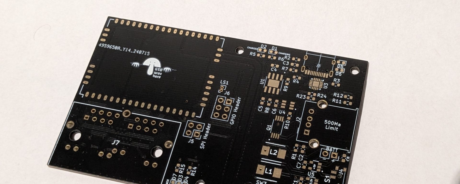
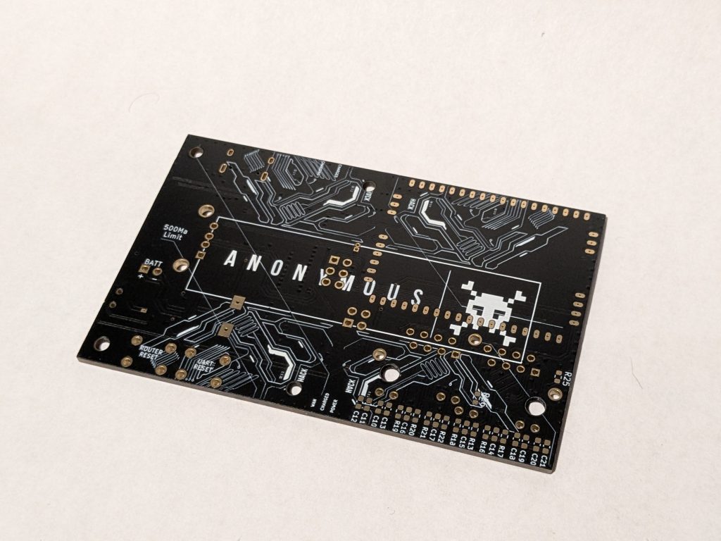
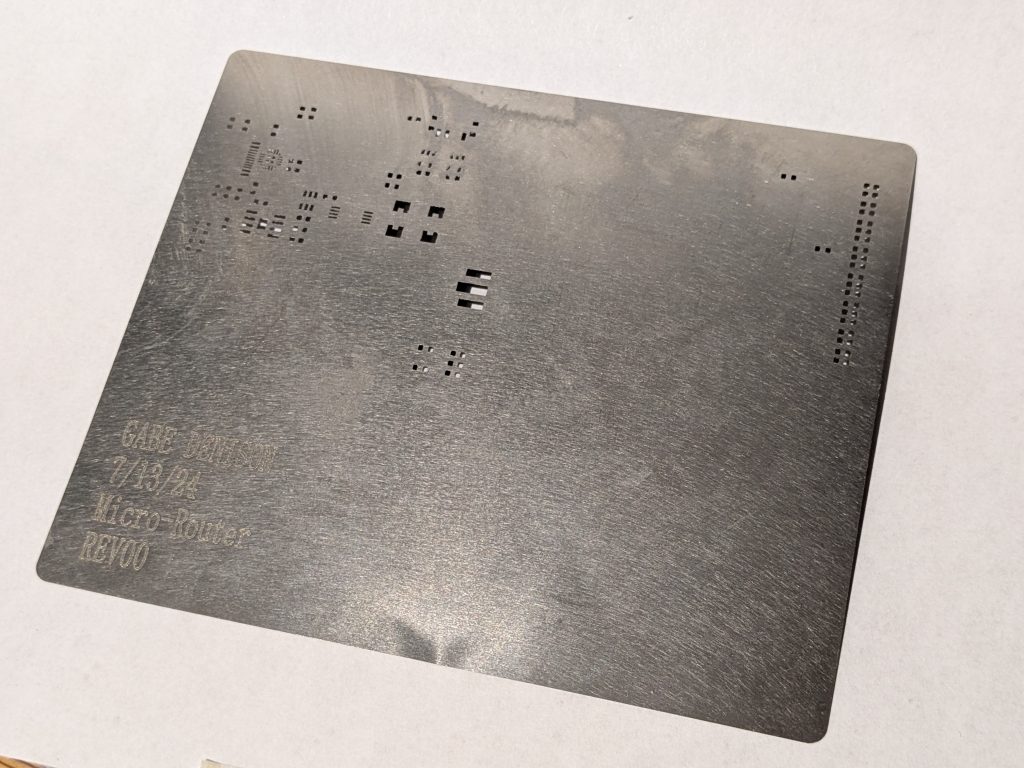
The board was designed with hand assembly in mind, so 90% of the components are on one side of the board to make stencil soldering most effective. The back of the board has only a row of 0603 Cap and resistors used to decouple the RJ45 signals. These were pretty easy to hand solder and, with a 3d printed rig, it could even be possible to stencils both sides. It was also designed with default 1.6mm thickness to lower the price of the SMA connector (1.6mm edge connectors are fairly common) and avoid more fees for non-standard board stack-up.
All of these measures were pretty successful; even with a stencil, the order was only $35. After a few weeks, the boards arrived and looked good. The only error was the stencil did not have the cutout for the Carambola 2. I failed to communicate to the manufacturer that I wanted this footprint included. Although it was a little but of a inconvenience it was not hard to drag solder the module in.
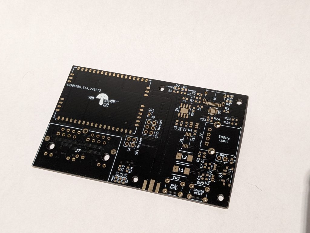
The first boards arrived, and they looked good. The only concern I had was case design. I did not stand the ports off at all. With some clever case design this was overcome but it definitely complicated the processes a lot. The other problem was I ended up with the wrong footprint for the DW01A when I built the first board, but ordered them in bulk when purchasing parts. I was faced with two options, either rev the board layout or reorder the correct footprint.
On top of all that, I found was the TLL to USB Bridge was completely miss-wired. This seems to just have been the result of not reading the docs carefully. Unfortunately this required a board rev to fix, but it was rather noninvasive compared to fixing the DW01A. As such this had very little bearing on the decision to just reorder the correct package for the DW01A and only fix the TTL to USB Bridge. I am also taking this time to fix ton the of the ports so that they stand off the board the correct distance to make the case design easier.