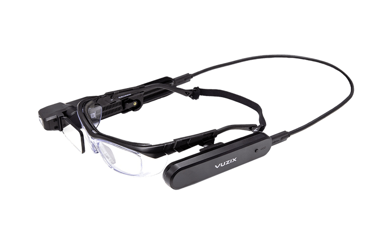
This project started as a way to create a better add-on AR display for prescription glasses. Most of the AR displays that are commercially available as add-on kits for prescription glasses are very bulky and extremely expensive. A Vuzix M4000 is well over $1,000 and is very impractical.
There are a lot of full AR glasses that are available for pretty cheap but are not very practical and don’t work with prescription glasses. I had been combing around for a custom solution for many years, but high-density OLED displays were not readily available, and even if you could find one, there was no documentation available to drive it. This severely limited the functionality of anything I could make. Finally, though, I found an AliExpress seller that had a very generic HUD listed.
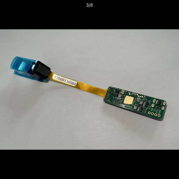
I did some poking around and was able to find a supplier that sold it directly. This proved to be rather helpful since the supplier seemed to be one of the fab shops making the drivers for the display and was able to provide extra documentation and an FFC connector instead of the HDMI port. This was something I have not found anywhere else. They also offered to rework the board for NRE as well, something I might take advantage of in the future. After a few weeks of waiting for it to arrive, I finally had my hands on the unit.
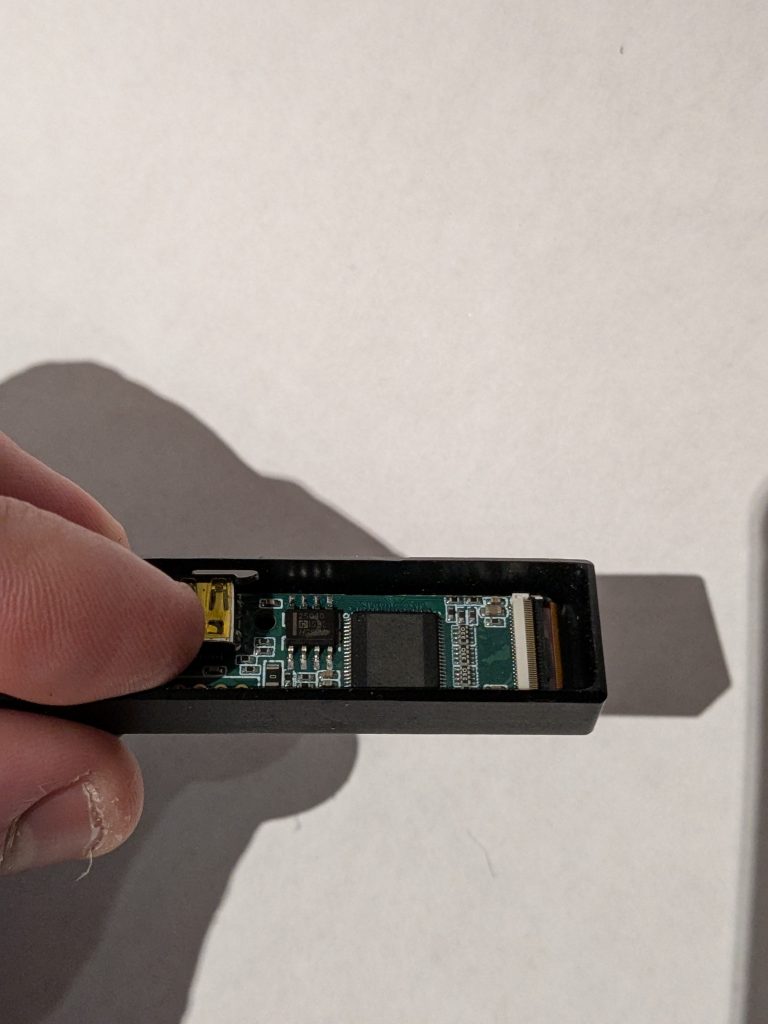
What arrived is definitely a first generation Chinese product. The main chip had all the identifying features lazed. This is a pretty common practice among Chinese fab shop to avoid clones of there boards being made. Also the optic was potted to the display with some kind of resin, but I’m still no really sure what the optic is off of the mounting features are definitely for something specific and not just generic mounting. This did provide a bit of a challenge when mounting the display/optic the housing. Other than that the display was exactly what I had been looking for. At a resolution of 600*400 it was possible to read text put on the display of just use it as a second display for my computer.
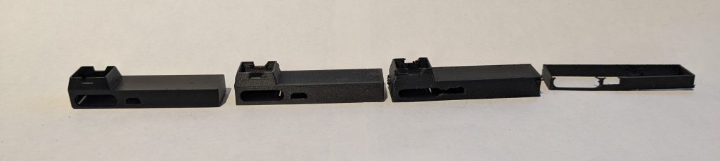
The next step was to make a housing. On its face this may look simple but it is actually very challenging. The biggest concern was weight. If it weighed any more than a few gram it would be uncomfortable to use. This limits materials to aluminum or titanium due to the density. Since the supplier was unable to provide a 3D model of the optic I resorted to trial and error. Using a 3D Printer I created several revision of the part to fit check it with the optic.
During the conceptualization of the Scouter I had a few design points I wanted to hit. I wanted to be as small and lite as possible. I was also trying to make a device that is somewhat stylish but dose not draw a lot of attention. This was almost as important as weight. I wanted to be use this device as a second display on a plane or while working on the go. But I did not want to draw any more attention than necessary to the device or myself. Some inspiration was drawn from the Scouter that can be seen in the popular DBZ Series.
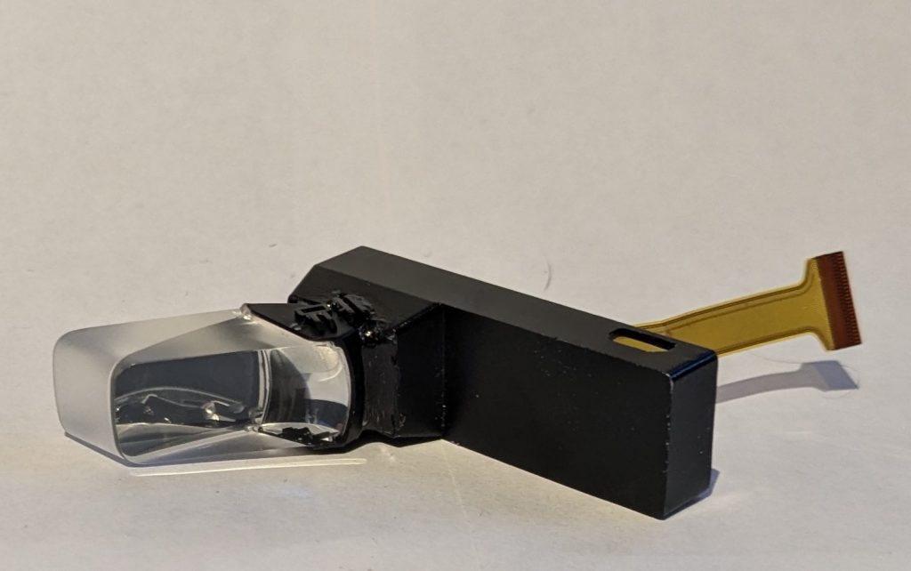
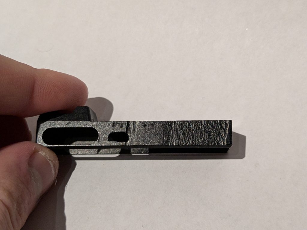
After neuroses attempts I was confident in the fitment and sent the design off to a fab shop to have it milled in low grade aluminum. At the time I did not have a way to draw a engineering drawing but the fab house was willing to accommodate me and let me submit a STEP file. Due to the price I opted for aluminum since titanium was far more expensive. However I did opt for anodizing the part black. After a few weeks the housing showed up.

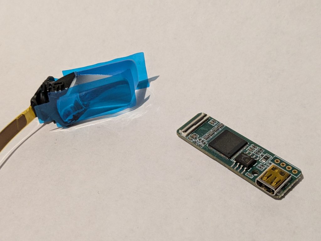
I decided to use marine epoxy to a-fix the display to the frame. Unfortunately This was were the flaws in my design reared their head. I had original planned to fold the ribbon and pot it and the driver into the “frame”. Unfortunately the ribbon was way to fragile to fold and instantly killed the display. (or so I thought)
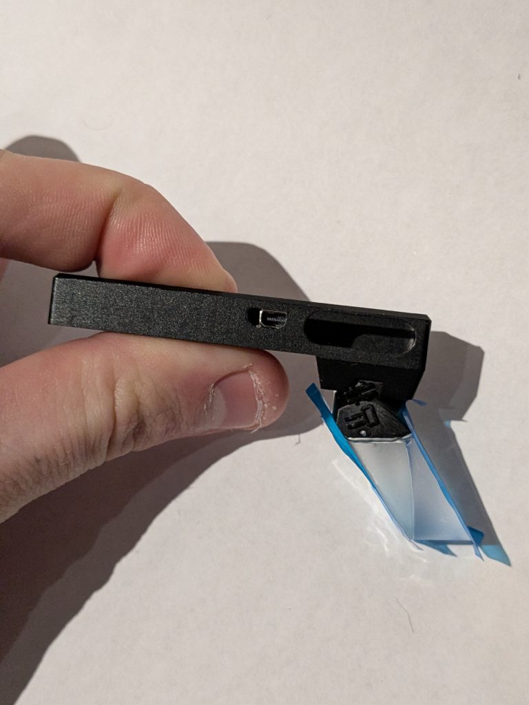
This caused a full re-render of the frame with only one soft bend in the cable. I also used this opportunity to add a magnetic POGO pin connector. This tied into a labeled 5v power rail on the driver PCB. Normally the driver board revives power from the HDMI port but the 5v rail is not always present across all HDMI ports. By adding this POGO connector I am able to power the device even if the the HDMI port doesn’t support it or I can use it to power small accessories like a ear piece. It also may come in handy if I decide to make more wearable tech.
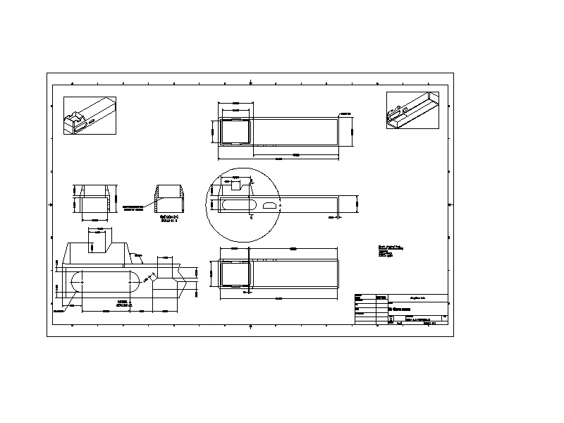
A new challenge reared it’s head while I was working with the machinist to have the new housing made. Originally I was able to just send a STEP file as the reference document however I needed more than .5mm accuracy for the new POGO pin connector to ensure proper fitment. At the time though I had never made a engineering drawing. Lucky for me though a co-worker was a expert and was able to guide me through the processes. It took a few hours but I was able to draft a drawing with all the pertinent info on it.
After a few weeks the machinist shipped out the new iteration. It looked quite good, I order 5 at a time to meet minimum amount for the machine shop (believe it or not ordering 5 from overseas is still cheaper than local services). As you would expect from such a small part there are some that had some small artifacts in the surface finish. Ultimately this isn’t a big deal though, since I just use the best one anyways.
This was superposed to be the final revision but I apparently was not so lucky. After a fit check I found that I under estimated the length of the ribbon cable. This lead the the HDMI port not lining up correctly. This unfortunately was rather inevitable. There is no drawings available for the driver board as it is a pretty uncommon/new part from Chinese fab shops. Thus they will not provide any more than the basic PCB size with no other features listed. This means most of my fitment work is just trial and error. While I was making this second revision of the housing I only had the old display that was epoxied into the failed first revision of housing. This meant I had to estimate the second revision of the housing, as the display assembly cost in excess of $200 and I was trying to hold out on buying a new display.
This unfortunately is a bit of a setback, I will have to re-render the housing for a third revision. This also comes with the need to re-make the drawing. All of this is going to have to be expedited as the Chinese new year is quickly approaching and the shop I have been using will likely be closed for at least a month. Fortunately the I believe this is possible as the changes that need to be made are pretty minimal.
This was were things took a bit of a turn. In a last ditch effort I tried the failed display that I had potted in my REV 1 housing with the new driver board I ordered for the new REV 2 housing. To my surprise and frustration it worked totally fine. In a effort to not waste the prism assembly I decided to use the driver board that I had and finish the REV 1 unit. A driver board is only $65 while a LCD/Prism is +$200.
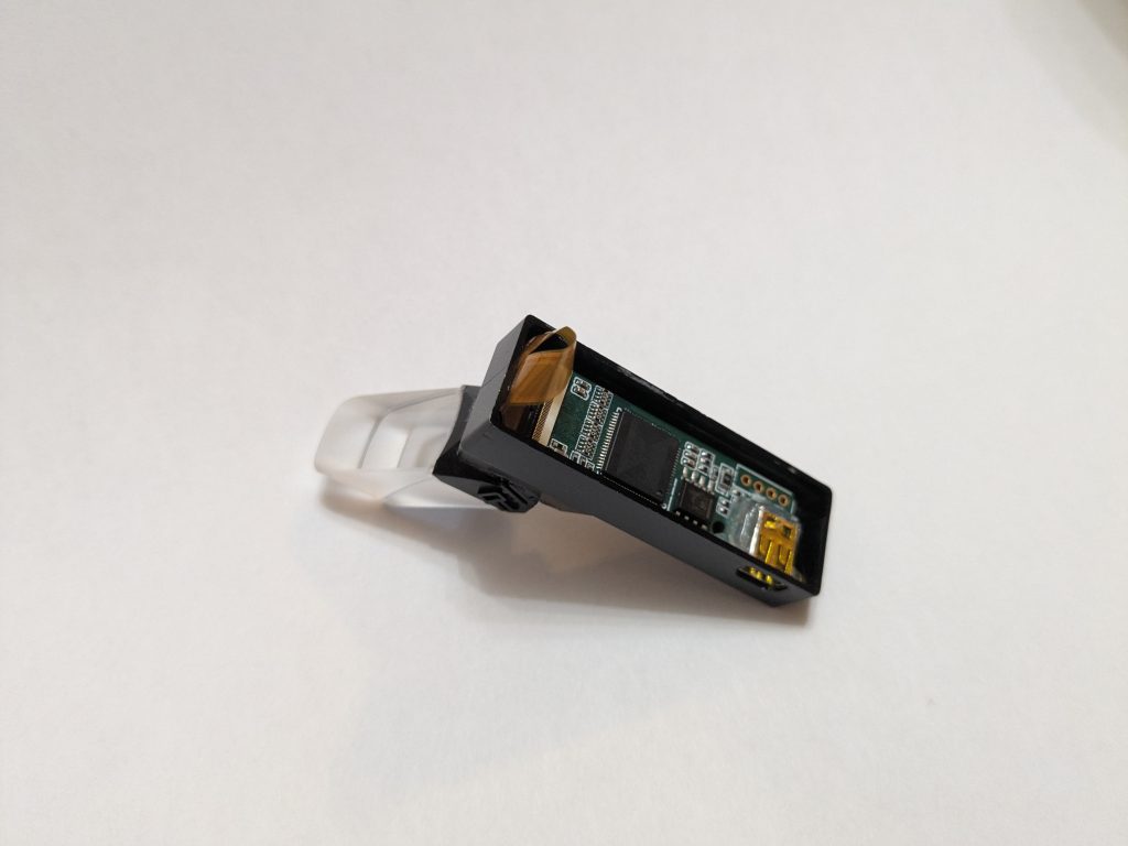
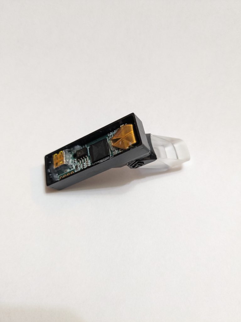
I placed a layer of kapton tape Under the PCB to keep it from shorting to the aluminum housing and glued the driver in with some super glue. You can see some extra glue around the HDMI port. This was to keep it sealed from the marine epoxy used to pot the entire thing. Without it you risk epoxy filling the port and rendering the entire thing useless. As a secondary layer of protection I also filled the port with Molykote 111. Molykote 111 is a dielectric and can be cleaned out with a little IPA, it acted as a final layer of protection from leakage. The complex ribbon cable folds can also be seen in the above pics. I had to use a little super glue there as well to hold it all in place and keep it from poking out when potted it.
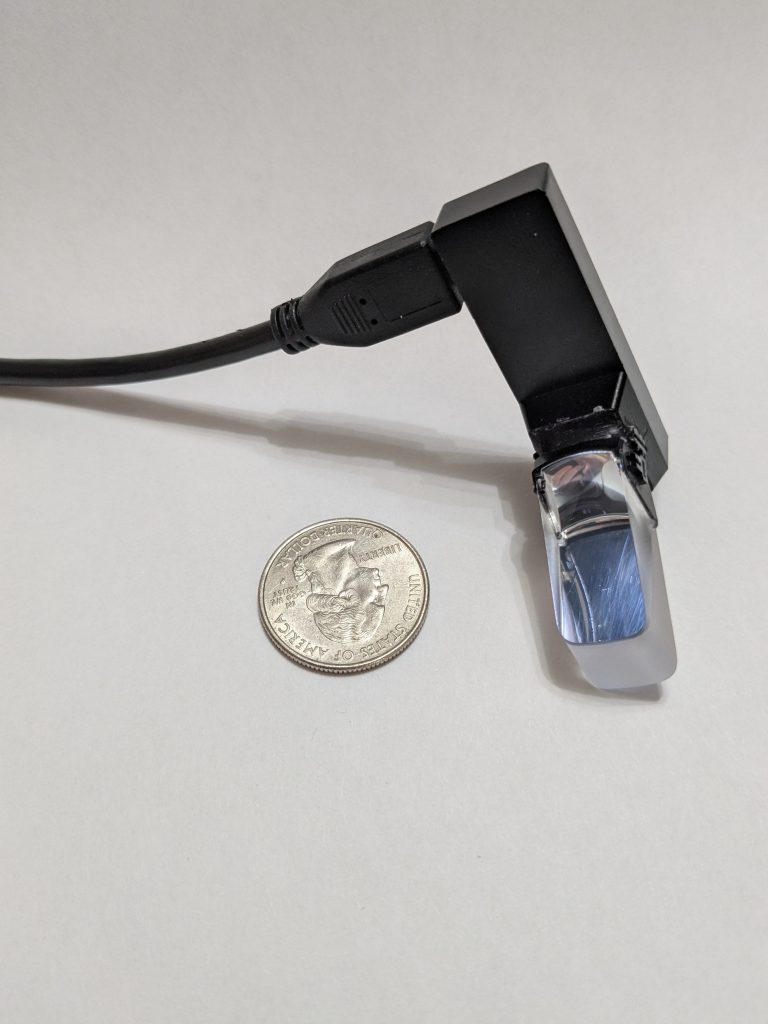
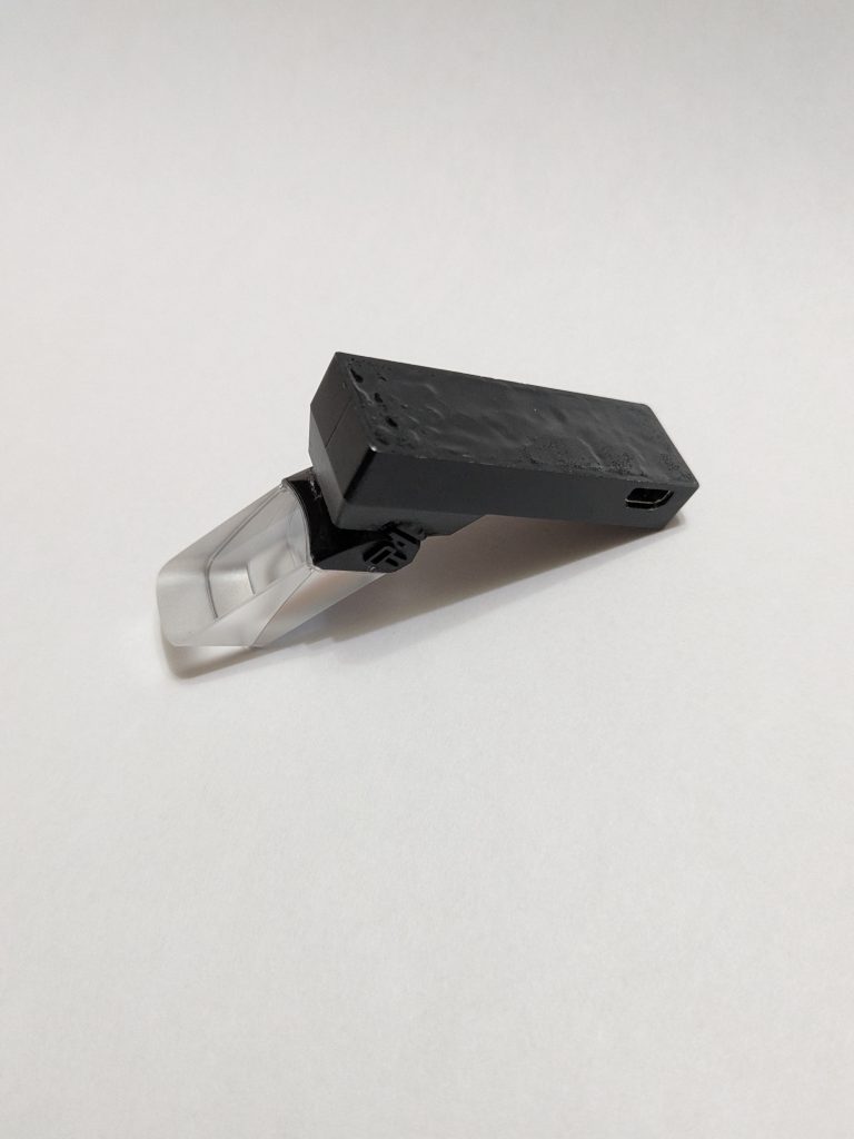
The final step was to pot the entire unit. This went off without a hitch surprisingly, I potted the unit and then used a syringe of IPA to clean the HDMI port out. After plugging it in to my PC Everything worked as it should. It is extremely small and only comes in at a weight of XXX. Overall I would call it a success. I will likely make REV 2 especially since I have a extra prism/LCD module kicking around but a more pressing concern is making the clip to mount it glasses.